

List of Sources:
- Young et al., 20201
- Images generated by WordPress AI
Table of Contents:
Torque (Young et al., 2020)
Similar to how a net force is required to provide linear acceleration to an object undergoing translational motion2, a net torque on an object causes angular acceleration. Thus, torque is a type of force that affects the rotational motion of an object.
To understand the effects of torque on an object, in addition to it’s magnitude and direction, you need to know the point at which it is being applied to the object. For instance, it is easier to open a door if force is applied farthest from the hinges.
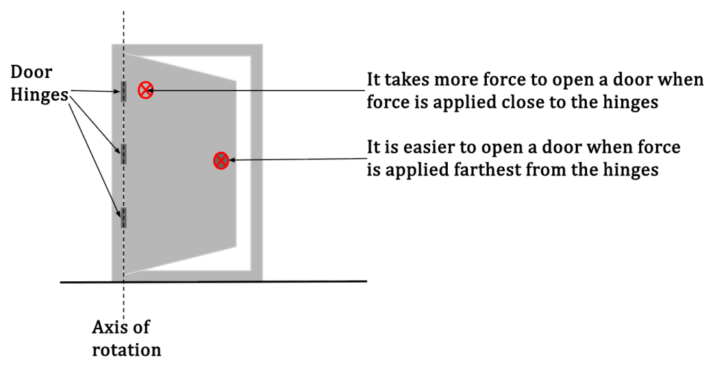
In Figure 1, we can say that a greater torque in applied to the door when force is exerted farthest from the hinges. Another example is that of a wrench that is used to tighten or loosen bolts.
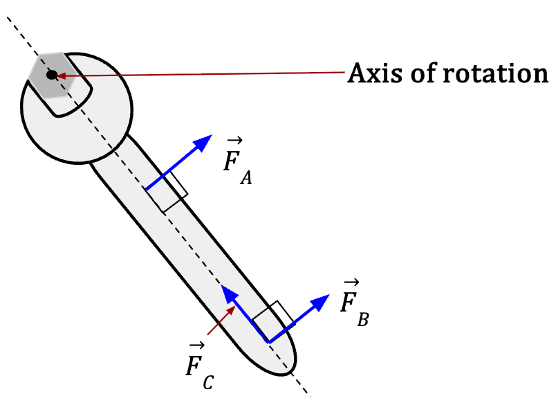
Notice in Figure 2 that when force is applied along the dotted line (), it has no effect on the rotational motion of the wrench. Thus, only the perpendicular component of applied force affects rotation about the rotational axis.
Torque is often donated by the Greek letter tau (). In order to calculate torque, we need to determine the elements that affect the rotational motion about an axis when a force is applied;
- The magnitude of applied force: Larger is the magnitude of applied force (F), large will be it’s affect on the rotational motion of the object in question and thus, larger will be the torque. In other words, torque is directly proportional to the applied force,
- The perpendicular distance between the axis of rotation and the line of action3: Larger is the perpendicular distance4 (l), larger will be it’s affect on the rotational motion and larger will be the applied torque. In other words, torque is directly proportional to this perpendicular distance, .
For a force (F) that is applied at a perpendicular distance (l) from the axis of rotation, torque is given by;
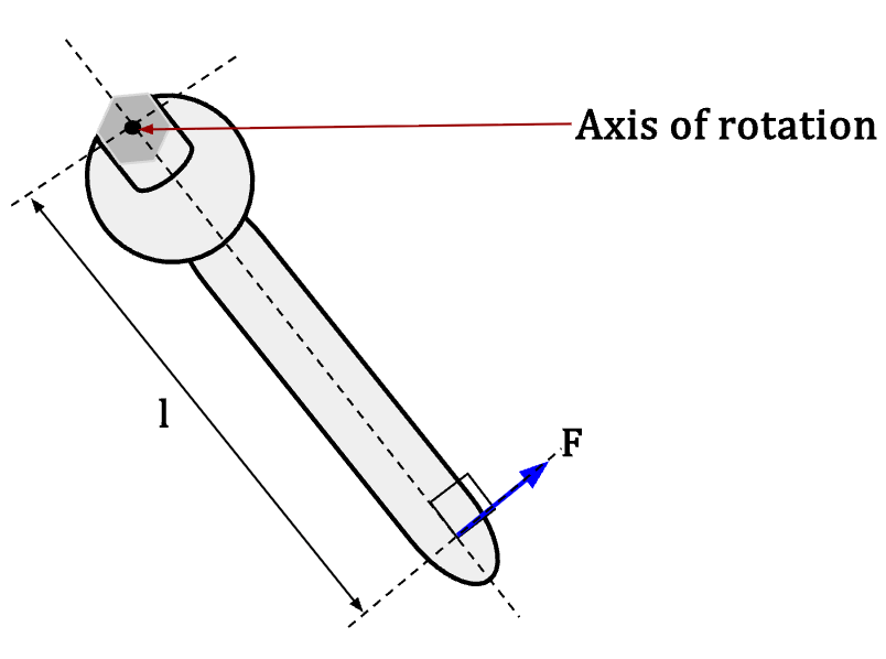
Thus, torque is defined as the product of magnitude of applied force (F) and the perpendicular distance (l) between the rotational axis and the line of action.
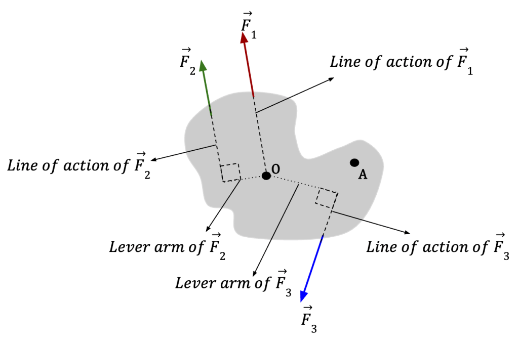
In Figure 4, force and produce rotation in the body about point O but force does not. This is because the line of action of passes through point O and it’s lever arm (l) equals zero and so does the torque. Additionally, if the magnitude of and is the same then will produce a larger torque than because it’s lever arm (l) is longer.
Note: It is important to note that torque is defined with respect to a point. For instance, in figure 4 produces zero torque about point O but it is not zero about point A. In other words, if the body in figure 4 is initially at rest then causes no rotation about point O but it will cause rotation about point A.
If we take counterclockwise rotation to be positive, then if a force (F) about a given point produces counterclockwise rotation, then the calculated torque will be positive, in other words, , but if a force produces clockwise rotation, then the calculated torque will be negative, or, .
The direction of torque () can be obtained using the right hand rule (see figure 5).
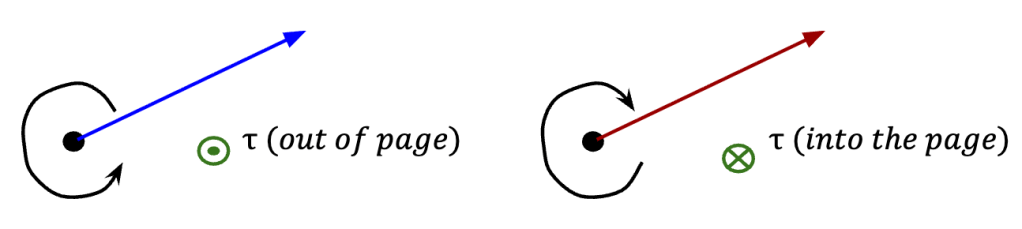
The SI unit for torque is newton-meter (Nm). The SI unit of work and energy, joule (J) is also equal to Nm but refrain from expressing torque in terms of joule because torque is not a form of work or energy.
Calculating torque of a rotating body:
Consider a rod attached to a stationary object, such that the rod is free to move about a point O (see Figure 6). A force is applied along the free end of the rod at point P which is at a location with respect to point O. The force causes the rod to turn in counterclockwise motion and thus, the torque is positive and directed out of page. The rod and hence make an angle with respect to the line of action of .
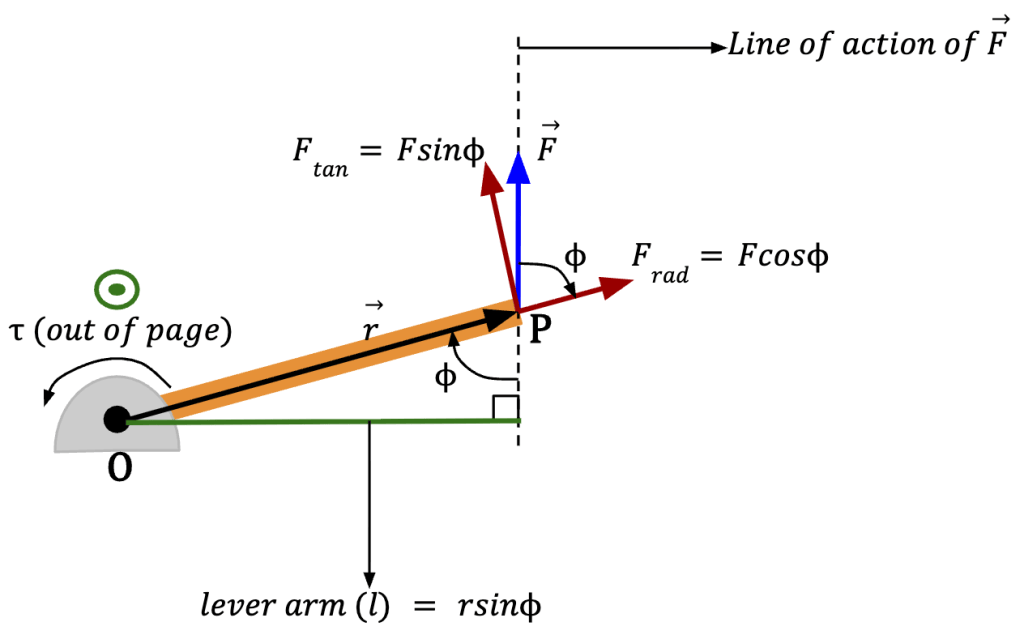
The torque can then be calculated in three ways:
- Since force F is given, if we can determine the magnitude of the lever arm (l), torque can be calculated using the formula; .
- If we can determine the angle between and , then you can see in figure 6 that the lever arm, and torque then equals; .
- We can break force into it’s component form: a radial component () that lies along the same direction as and a tangential component () that is perpendicular to the 5. From figure 6, we can see that and . Now, using the relationship established in bullet point 2, we can calculate torque as; .
Bringing it all together;
where is the magnitude of torque generated due to the applied force about point O, F is the magnitude of the applied force, l is the magnitude of the lever arm, r is the magnitude of or distance of the point at which force acts from the rotational axis, is the angle between and , and is the tangential component of applied force, .
Torque as a Vector
From the definition of cross or vector product, we can write torque as;
Thus, torque in it’s vector form is defined as the cross product between the applied force and the vector location of the point at which this force is applied with respect to the rotational axis, given by . While the magnitude of torque is given by , it’s direction as discussed above is given by the right-hand rule.
According to the rules of vector product, the direction of torque () is always perpendicular to both and . Alternatively, if both and lie in the plane that is perpendicular to the axis of rotation, then will lie along the same direction as the rotational axis (see Figure 7).
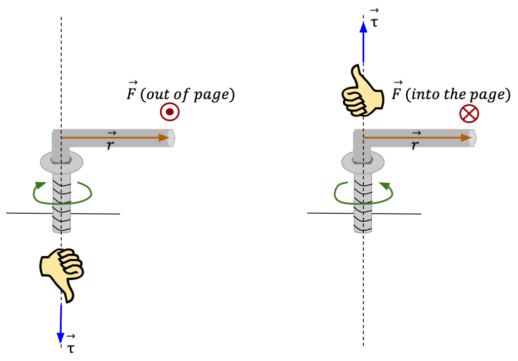
In figure 7, when force is applied such that the allen wrench undergoes clockwise rotation, is downwards (or negative) and that is the direction in which the screw moves in (left image). Conversely, when force is applied such that the allen wrench moves in a counterclockwise motion, is positive and the screw moves in the upwards direction (right image).
Torque and Angular Acceleration for a Rigid Body (Young et al., 2020)
Let’s develop a relationship between the torque applied to a rigid body and the corresponding angular acceleration of the body as it rotates.
- Young, H.D. et al. (2020) Sears and Zemansky’s university physics: With modern physics. 15th edn. Boston: Pearson. ↩︎
- Translational motion is a type of motion that an object undergoes, such that the whole object moves in the same fashion through space. In other words, every single part of the object travels the same distance with same speed and in the same direction without spinning. ↩︎
- The direction or line along which a force vector lies is referred to as the line of action. ↩︎
- This perpendicular distance is sometimes referred to as the lever arm or moment arm. ↩︎
- The tangential component has to be the one that is perpendicular to the because when the rod turns in a counterclockwise motion, it’s free end traces a circle and is tangent to each point on this circular path. ↩︎
 Understand the cosmos