

List of Sources:
- Young et al., 20161
- Images generated by WordPress AI
Table of Contents:
- Position and Velocity Vectors (Young et al., 2016)
- The Acceleration Vector (Young et al., 2016)
- Projectile Motion (Young et al., 2016)
- Motion in a Circle (Young et al., 2016)
- Relative Velocity (Young et al., 2016)
Position and Velocity Vectors (Young et al., 2016)
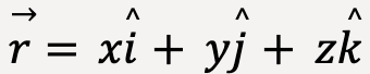
Consider a particle located at point P somewhere in the three dimensional Cartesian coordinate system. The position vector, ![]() is graphically represented by an arrow with its tail at the origin and tip located at point P. Unit vector representation of
is graphically represented by an arrow with its tail at the origin and tip located at point P. Unit vector representation of ![]() in three dimensional space is as follows:
in three dimensional space is as follows:
 ….(1)
….(1)
where x is the distance of the particle from the origin along the x-axis, y is the distance of the particle from the origin along the y-axis and z is the distance of the particle from the origin along the z-axis. ![]() is the unit vector in the x-direction,
is the unit vector in the x-direction, ![]() is the unit vector in the y-direction and
is the unit vector in the y-direction and![]() is the unit vector in the z-direction.
is the unit vector in the z-direction.

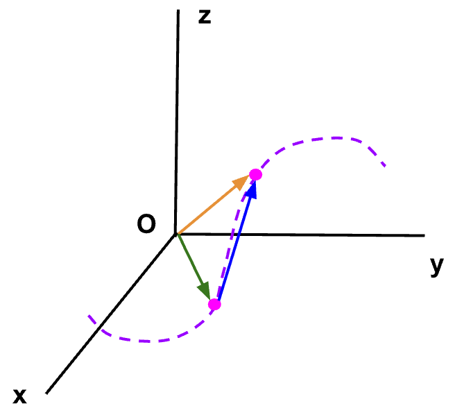
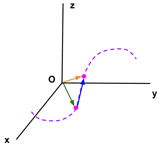
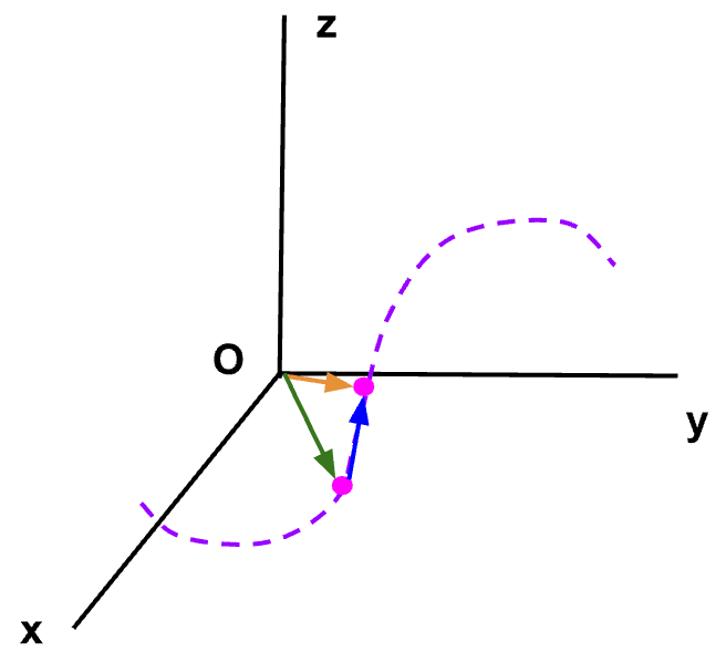
 are shown in 3D Cartesian coordinate system on the left. The direction of the three components is visualized in 3D space and is shown on the right.
Note: The three components of ![]() can be thought of as three separate vectors with
can be thought of as three separate vectors with  along the x-direction,
  along the y-direction and
  along the z-direction.
 ![]() is then given by the vector addition of , and . As discussed earlier, vectors can be added graphically with resultant vector, in this case,
is then given by the vector addition of , and . As discussed earlier, vectors can be added graphically with resultant vector, in this case, ![]() , that originates at the tail of the first vector, in this case, and ends at the tip of the last vector, in this case, (See figure 1, image on the right).
, that originates at the tail of the first vector, in this case, and ends at the tip of the last vector, in this case, (See figure 1, image on the right).
Consider a particle at point P1 during time t1 such that it’s position vector is given by ![]() 1 = x1
1 = x1![]() + y1
+ y1![]() + z1
+ z1![]() . After some time, the particle is now at point P2 at time t2 with position vector
. After some time, the particle is now at point P2 at time t2 with position vector ![]() 2 = x2
2 = x2![]() + y2
+ y2![]() + z2
+ z2![]() .
.
The displacement,  during time interval, Δt = t2-t1, is then given as,
 ….(2)
….(2)
The average velocity, ![]() av defined as displacement divided by the time interval can be calculated as follows:
av defined as displacement divided by the time interval can be calculated as follows:
 ….(3)
….(3)
Note: The x-component of ![]() av is given by (x2-x1)/(t2-t1) which is the same as the expression computed earlier for vav(x).
av is given by (x2-x1)/(t2-t1) which is the same as the expression computed earlier for vav(x).
The direction of average velocity is in the same direction as the displacement vector.
The instantaneous velocity is given by average velocity in the limit that Δt goes to zero which is equal to the instantaneous rate of change of displacement vector with respect to time;
 ….(4)
….(4)
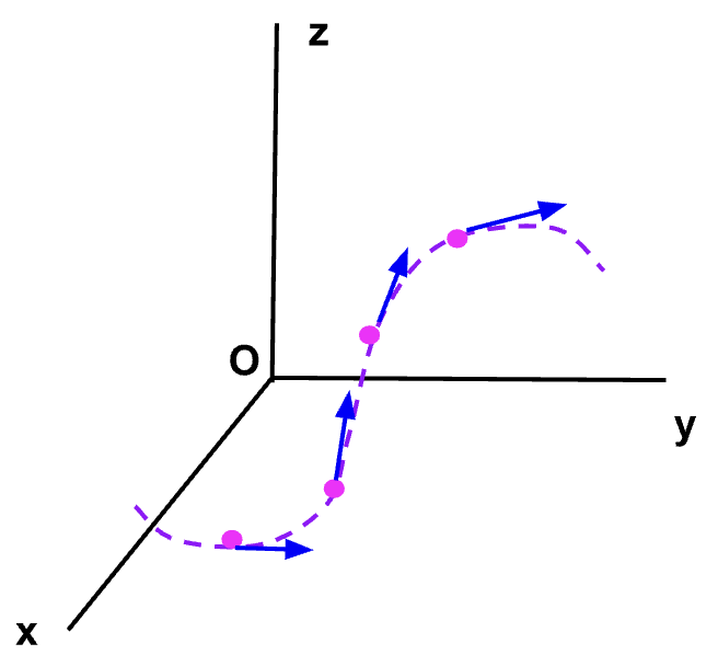
Magnitude of instantaneous velocity is equal to the speed of the particle at that instant. Direction of instantaneous velocity is towards the direction of the displacement vector, which in the limit that Δt goes to zero becomes tangent to the point at that instant.

Figure 2: While the particle moves along a curved path as shown in purple, if we start moving point P2 closer to point P1 such that Δt approaches zero, then (blue arrow) becomes tangent to the path and so does the instantaneous velocity,![]() (see below).
(see below).

Sometimes its more convenient to calculate the instantaneous velocity vector by evaluating each of its components individually.
The component form of instantaneous velocity vector can be written as;
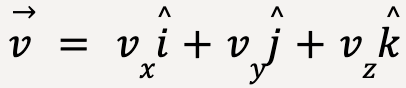 …..(5)
where 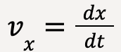 ,
,  and
and , such that the x-component of instantaneous velocity is equal to the time derivative of x-coordinate, y-component of instantaneous velocity is equal to the time derivative of y-coordinate and z-component of instantaneous velocity is equal to the time derivative of the z-coordinate2. Therefore,
 …..(6)
The magnitude of instantaneous velocity or the speed of the particle at that instant in 3D can be determined using Pythagoras theorem because the x-, y-, and z-components of ![]() are mutually perpendicular to each other;
are mutually perpendicular to each other;
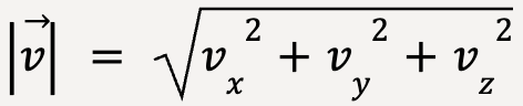 …..(7)
In two-dimensional space,
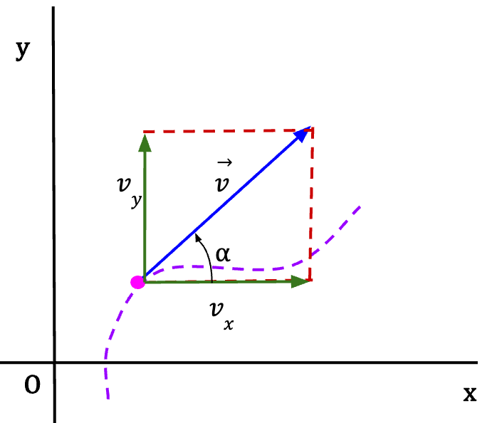
 form the two sides of a right angle triangle.
Using Pythagoras theorem, the magnitude of instantaneous velocity in 2D is given as;
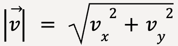 …..(8)
The direction of instantaneous velocity can be stated in terms of angle α such that;
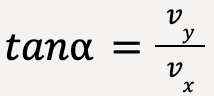 …..(9)
The Acceleration Vector (Young et al., 2016)
It is important to note that a particle is said to be accelerating when:
- the magnitude of velocity is changing with time but the direction stays the same
- the direction of the velocity is changing with time but the magnitude stays the same
- both magnitude and direction of velocity are changing with time
The average acceleration of a particle in 3D is given as:
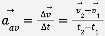 …..(10)
where at time t1, the particle is at point P1 with a velocity given by ![]() 1 and at time t2, the particle is at point P2 with a velocity given by
1 and at time t2, the particle is at point P2 with a velocity given by![]() 2.
2.
The direction of average acceleration vector is in the same direction as the change in the velocity vector,  .
.
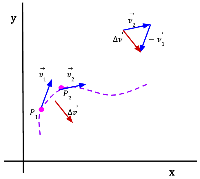
Figure 5: If the particle is moving along a path shown using the purple dashed line such that at time t1 its moving with velocity ![]() 1 and at time t2 with velocity
1 and at time t2 with velocity ![]() 2, then the resultant change in velocity, =
2, then the resultant change in velocity, = ![]() 2 –
2 – ![]() 1 is given by the red arrow which is also the direction of the average acceleration vector.
1 is given by the red arrow which is also the direction of the average acceleration vector.
Let’s say we start moving point P2 closer to P1 such that the time interval Δt becomes infinitesimally small, then in this limit the average acceleration of the particle is equal to the instantaneous acceleration at that instant.
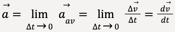 …..(11)
If the path is straight, the direction of instantaneous acceleration is along the path but if the path is curved, the direction of instantaneous acceleration is towards the concave side of the path or towards the inside of the curve.

Figure 6: For straight path, the change in velocity vector and instantaneous acceleration are along the path taken by the particle.
Figure 7: For curved path, the instantaneous velocity vector is always tangent to the curve at a point and instantaneous acceleration points towards the inside of the curve.

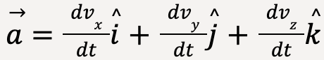
The instantaneous acceleration vector can be stated in component form as follows:
 ……(12)
where  ,
,  and
and  because
  or instantaneous acceleration is equal to the time derivative of velocity vector.
Thus, instantaneous acceleration can also be written as;
 ……(13)
We also know that instantaneous acceleration is the second time derivative of displacement vector, 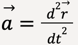 ,
,
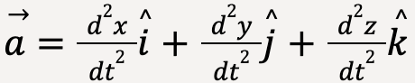 ……(14)
Parallel and Perpendicular Components of Acceleration
When a body is moving along the curved path, it is useful to think of instantaneous acceleration in terms of a component parallel to the path and a second component perpendicular to the path taken by the particle.

Figure 8: The parallel component of acceleration, ![]() , is in the same direction as the tangential instantaneous velocity and thus,
, is in the same direction as the tangential instantaneous velocity and thus, ![]() gives information about changes to the particle’s speed. On the other hand, the perpendicular component of acceleration,
gives information about changes to the particle’s speed. On the other hand, the perpendicular component of acceleration, ![]() gives information about changes to the particle’s direction.
gives information about changes to the particle’s direction.
If ![]() = 0, the particle’s magnitude of velocity changes while the direction stays the same. If
= 0, the particle’s magnitude of velocity changes while the direction stays the same. If ![]() = 0, the particle moves with constant speed along a curved path.
= 0, the particle moves with constant speed along a curved path.
The three cases for a particle moving along a curved path are shown below:
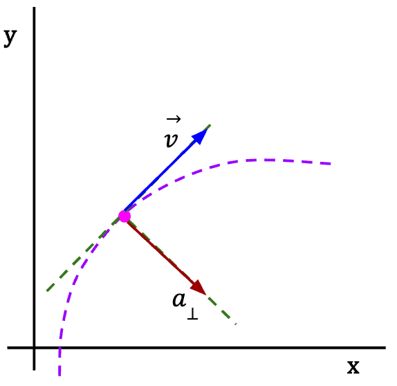
Figure 9: When acceleration is perpendicular to the velocity vector, particle moves along a curved path with a constant speed (the parallel component of acceleration in this case is zero). Alternatively, if a particle is moving along a curved path with constant speed, we can tell that acceleration vector must be perpendicular to velocity (or along the normal to the curve).
Figure 10: If the acceleration vector is pointing ahead of the normal to the curve, this means that the parallel component of acceleration is in the direction of the velocity vector and the particle is speeding up as it moves along the curved path. Alternatively, if the particle is speeding up as it moves along a curved path, the acceleration vector has a parallel and a perpendicular component.
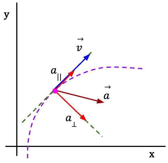

Figure 11: If the acceleration vector is behind the normal to the curve, then it has a parallel component in a direction opposite to the velocity vector and the particle is slowing down as it moves along the curved path. Alternatively, if a particle is slowing down as it moves along a curved path, then the acceleration vector is behind the normal to the curve and has a parallel and a perpendicular component.
Projectile Motion (Young et al., 2016)
A projectile is defined as a body that is launched with an initial velocity and subsequently travels exclusively under the influence of gravity and air resistance. The path taken by the projectile is referred to as its trajectory.
Idealized Model of a Projectile
The most simple model of a projectile makes the following assumptions:
The Trajectory of an Idealized Projectile
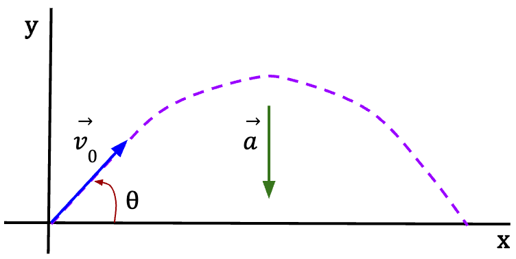
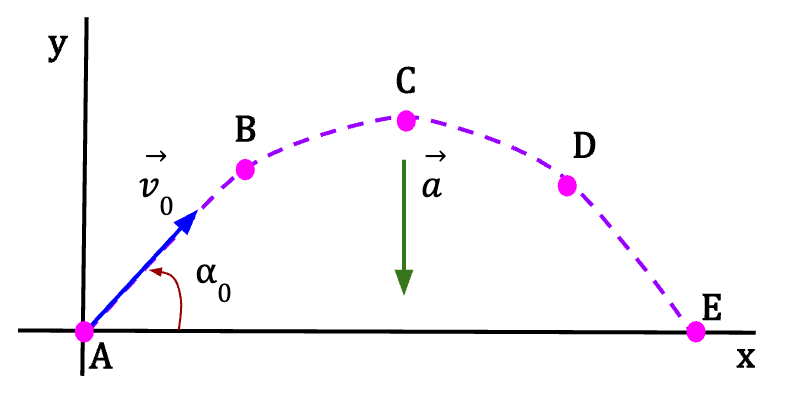
Figure 12: The trajectory of an idealized projectile is shown in purple as it travels under the influence of gravity alone, such that the component of acceleration in y-direction is equal to g (=9.8m/s2) while the component of acceleration in the x-direction is equal to zero. This means that projectile motion is two-dimensional because gravity cannot cause sideways acceleration (in the z-axis) and motion is confined to a vertical plane.
The best way to analyze projectile motion is to study the motion in the horizontal direction and motion in the vertical direction separately. It is possible to examine them separately because a projectile’s motion in the two directions is independent of one another. In other words, motion along the horizontal direction does not affect motion along the vertical direction and vice versa.
Proof:
If you drop two balls from the same height such that the initial x-velocity of the first ball is zero while the initial x-velocity of the second ball is non-zero (initial y-velocity of both balls is zero), you will see that the balls will have the same y-position at every instant of time regardless of what occurs in the x-direction (see below).
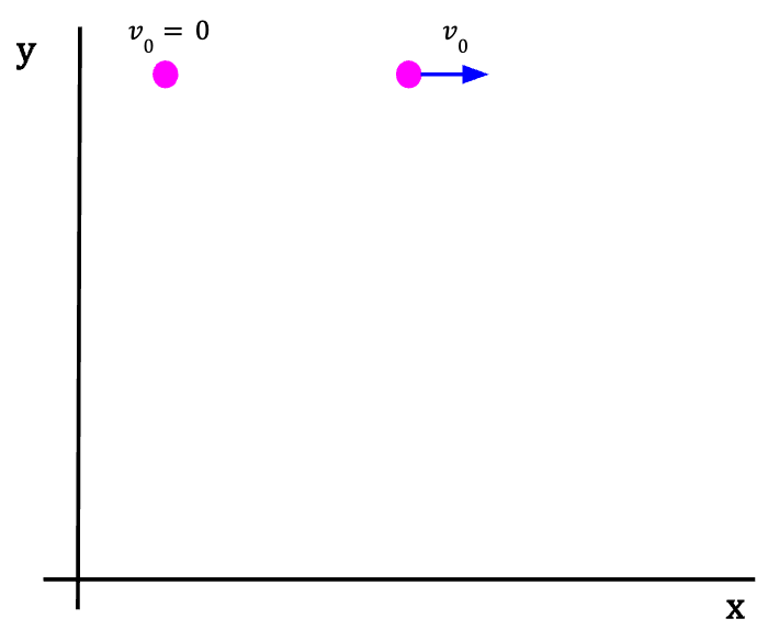
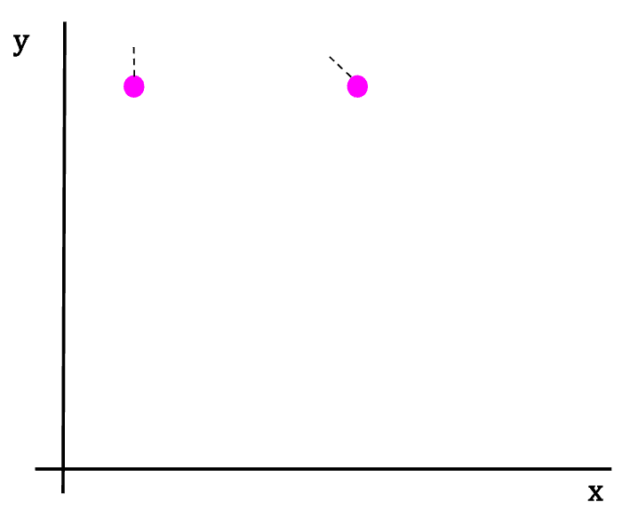
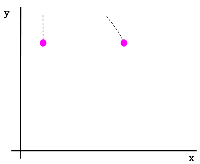


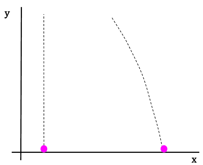
This means that problems involving projectile motion can be solved by analyzing the vector relationships in x- and y-direction separately.
Components of Acceleration
The horizontal component of acceleration, ![]() for idealized projectile motion will always be zero;
for idealized projectile motion will always be zero;
 …..(15)
If we take positive y-direction to be upwards, then the vertical component of acceleration, ![]() for idealized projectile motion will always be equal to the negative of acceleration due to the Earth’s gravity;
for idealized projectile motion will always be equal to the negative of acceleration due to the Earth’s gravity;
 ……(16)
where g is approximately equal to 9.80 m/s2.
Since acceleration in constant in both x- and y-directions, we can use the equations of motion with constant acceleration.
| Horizontal (x) direction (positive to the right) | Vertical (y) direction (positive taken to be upwards) |
 But ax = 0;  | 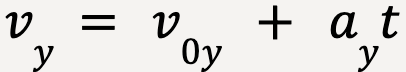 But ay = -g 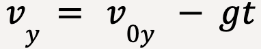 |
 But ax = 0;  | 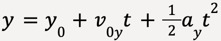 But ay = -g 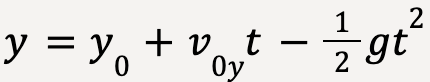 |
In Figure 12:
Let the projectile be launched with a velocity ![]() 0 at time t0 = 0 from the origin (x0 = y0 = 0).
0 at time t0 = 0 from the origin (x0 = y0 = 0).
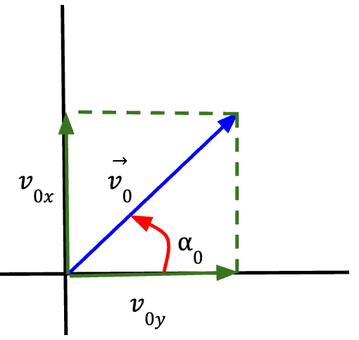
 at an angle
  with the horizontal.
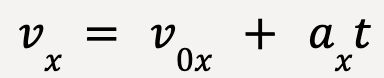
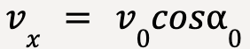
 Thus, the x-component of projectile’s velocity can be written as:
 ……(17)
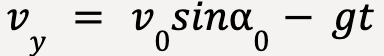
and the y-component of projectile’s velocity can be written as:
 …….(18)
| Horizontal (x) direction (positive to the right) | Vertical (y) direction (positive taken to be upwards) |
 |  |
 |  |
As stated previously, problems involving projectile motion can be solved by considering what happens in x- and y- direction separately.
Analyzing the values in the table;
The x-velocity of the projectile does not depend on time and therefore is constant throughout. This makes sense because acceleration in x-direction is equal to zero. Since the velocity is constant, the projectile travels equal distance in equal intervals of time along the x-direction.
In the y-direction, velocity is changing because of acceleration due to gravity.
Analyzing Projectile Motion
In the y-direction:
The particle at point A is launched with a non-zero y-velocity which is directed upwards.
At point B, the y-component of the velocity is upwards while the acceleration due to gravity is directed downwards. Since the velocity and acceleration are acting in opposite directions, the projectile is slowing down as it moves towards the maximum y-position.
At point C, the y-velocity of the projectile goes to zero and it reaches maximum height. However, at this point, the acceleration due to gravity is non-zero and acting downwards. Note: The x-velocity of the particle is also non-zero which means the particle will travel further in the x-direction.
At point D, after reaching maximum, the particle starts moving downwards. Since the direction of velocity and acceleration are now the same, the particle is picking up speed as it moves downwards.
At point E, the particle reaches the ground with the same speed with which it was launched.
The distance of the projectile, r, at any point along its trajectory from the origin can be calculated using Pythagoras theorem:
 ……(19)
Velocity at any point along the trajectory can be computed using:
 ……(20)
The direction of the velocity vector can be calculated as follows:
 ……..(21)
Note: As discussed previously, the direction of the velocity vector is tangent to the trajectory at each point.
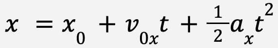
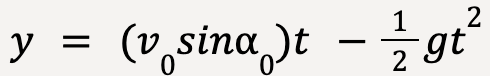
The equation for the trajectory in terms of x and y can be deduced by eliminating t using the following kinematic equations:
…..(22)
……(23)
Rearranging equation 22;
 …..(24)
Substituting equation 24 into equation 23;
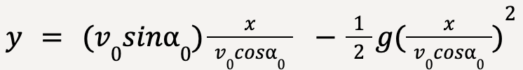 …..(25)
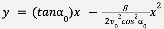 ……(26)
Since  ,
,  , g and
  are constants, equation 26 can be written as;
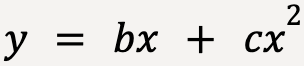 …..(27)
Equation 27 is a general form of a quadratic equation where b and c are constants. The graph of a quadratic equation is a parabola and thus the trajectory in the idealized model of a projectile will always be parabolic6.
Motion in a Circle (Young et al., 2016)
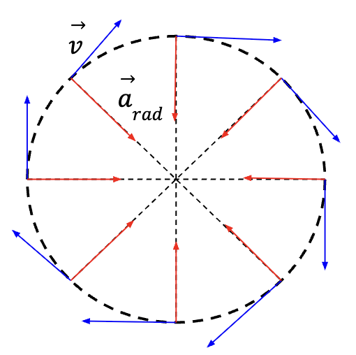
Uniform Circular Motion
When a particle moves along a circular path with constant speed, it’s referred to as uniform circular motion. There is a perpendicular component of acceleration acting inwards7 of the curved path causing the direction of the particle to change constantly. However, the parallel component of acceleration has to be zero since the speed of the particle is not changing. If there was a parallel component of acceleration acting on the particle, the particle would be speeding up or slowing down (see Figure 10 and Figure 11).
Magnitude of Acceleration in a Uniform Circular Motion
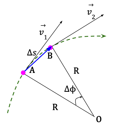
Figure 15: A particle moves from point A with velocity  to point B with velocity
  such that it covers a distance
 ![]() which corresponds to an angular displacement of
which corresponds to an angular displacement of ![]() in time interval Δt. The radius of the curved path is given by R and the speed along the path is constant.
in time interval Δt. The radius of the curved path is given by R and the speed along the path is constant.
The change in the velocity vector 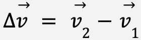 can be illustrated using a vector diagram as follows:
Figure 16: Vector addition diagram for is shown to the right. In Figure 15, since is perpendicular to line OA and is perpendicular to line OB, then![]() (Figure 15) and
(Figure 15) and ![]() (Figure 16) are same and equal to
(Figure 16) are same and equal to ![]() , which in turn means that the triangles AOB and CID are similar (for better clarification, see Figure 17 below).
, which in turn means that the triangles AOB and CID are similar (for better clarification, see Figure 17 below).
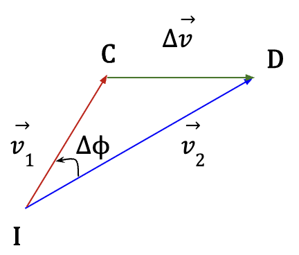
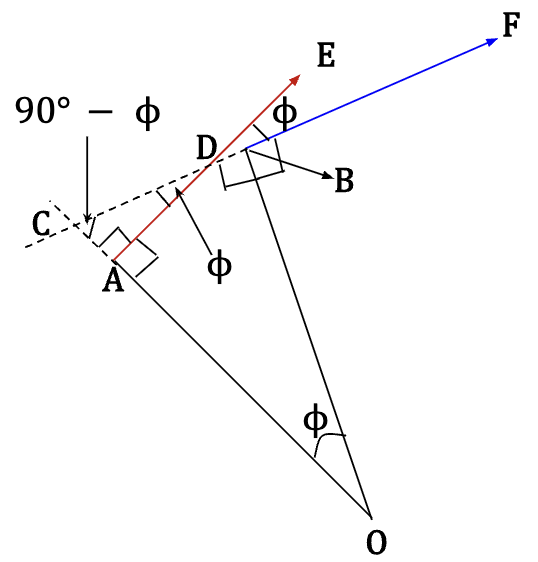
Figure 17: We know that ![]() =
= ![]() and
and ![]() and
and ![]() equal 90°. Now, extend the line from BF back to point C and extend OA backwards to point C such that
equal 90°. Now, extend the line from BF back to point C and extend OA backwards to point C such that ![]() and
and ![]() are equal to 90°. In
are equal to 90°. In ![]() ,
, ![]() is equal to
is equal to ![]() because angles in a triangle always equal to 180°. Consequently, in
because angles in a triangle always equal to 180°. Consequently, in ![]() ,
, ![]() equals
equals ![]() and since angles between two intersecting lines are equal,
and since angles between two intersecting lines are equal, ![]() =
= ![]() . In other words, the angle between red vector and blue vector is equal to
. In other words, the angle between red vector and blue vector is equal to ![]() .
.
Since ![]() (Figure 15) and
(Figure 15) and ![]() (Figure 16) are similar, the ratio of corresponding sides is equal. This means that:
(Figure 16) are similar, the ratio of corresponding sides is equal. This means that:
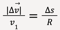 ……(28)
 …….(29)
The magnitude of average acceleration over time interval Δt is then given as:
 …….(30)
 …….(31)
Instantaneous acceleration at point A (Figure 15) is given by the limit of average acceleration as Δt becomes infinitesimally small and in this limit, Δs/Δt = v1.
 ……(32)
The expression for magnitude of radial acceleration at any point along the curve for uniform circular motion is given as:
 ……(33)
The direction of radial acceleration is always pointed towards the centre of the curve and is perpendicular to the velocity vector at any point along the curve.
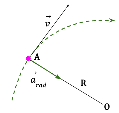
The instantaneous acceleration in the case of uniform circular motion is also referred to as centripetal acceleration because it is always pointed towards the centre of the curve.
Aside: Difference between Uniform Circular Motion and Projectile Motion

For both uniform circular motion and projectile motion, the magnitude of acceleration at each point or instant is the same. In case of uniform circular motion, the magnitude is always equal to square of the speed of the particle (v) divided by the length of the radius (R) of the circle (v2/R). On the other hand, in case of projectile motion, the magnitude of acceleration is always equal to g = 9.81 m/s2.
However, in case of uniform circular motion, the direction of instantaneous acceleration is always changing, but is perpendicular to the velocity vector at all times and is pointed towards the centre of the curve. On the contrary, direction of instantaneous acceleration in the case of projectile motion is always the same and is pointed downwards (y-direction) at all times. It is perpendicular to the velocity vector only at the highest point where velocity in the y-direction becomes zero and the particle only has velocity in the x-direction.
A Second Expression for the Magnitude of Acceleration in Uniform Circular Motion
Let T be the period of motion or time taken by the particle to travel around the circle once (one revolution), then the distance it covers during that trip is equal to the circumference of the circle which is given by 2πR where R is the radius of the circle.
The speed of the particle is then given by;
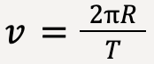 …..(34)
Plugging this into equation (33):
 ……(35)
Thus, the magnitude of uniform motion acceleration can also be computed using:
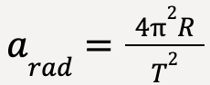 …….(36)
where R is the radius of the circle and T is the time period or time it takes for the particle to complete one revolution.
Nonuniform Circular Motion
If a particle moves in a circle at varying speed, it is referred to as nonuniform circular motion. The radial component of instantaneous acceleration is still given by v2/R. However, it is not constant along the curve because the speed (v) is changing. Since the radial component of acceleration is directly proportional to square of the magnitude of particle’s speed, its magnitude is greatest at points where speed is maximum.
Since the speed of the particle is changing, along with a radial component, instantaneous acceleration has a component parallel to the velocity vector (as discussed in Figure 10 and 11). However, in case of circular motion, the parallel component is referred to as the tangential component of acceleration or atan8.
The magnitude of tangential component is equal to the rate of change of particle’s speed and can be calculated as follows:
 …..(37)
If the speed of the particle is increasing, atan is in the same direction as the velocity vector but if the particle is slowing down, atan is in the direction opposite to the velocity vector. And finally, if the speed is constant, atan=0 which is defined as uniform circular motion.
Aside: Difference between  and
and 
They are not the same quantity. is the rate of change of speed of the particle and is zero when speed is constant. is the magnitude of instantaneous acceleration and is zero only when particle moves with a constant speed and along a straight line (direction is not changing).
For uniform circular motion,
is equal to zero and is equal to arad = v2/R.
For nonuniform circular motion,
is nonzero and is equal to  .
.
Relative Velocity (Young et al., 2016)
Velocity of an object can vary depending on observer’s motion, and is defined as relative velocity or velocity of the object relative to the observer. For instance, the velocity of a moving train observed by a stationary and a moving observer will be different. A train that appears to move forward for a stationary observer can appear to move backwards for an observer who is moving faster than the train in the same direction!
Relative Velocity in One Dimension
Frame of Reference
A frame of reference is defined as “a coordinate system plus a time scale”. Each observer forms their own frame of reference.
For example, if a passenger on a moving train starts to walk forward with a speed of 1.o m/s while the train moves forward with a speed of 5.0 m/s, the velocity of the passenger relative to the train will be 1.0 m/s but the velocity of the same passenger relative to a stationary observer standing on the side of the tracks will be 1.0 m/s + 5.0 m/s = 6.0 m/s.
Expression for Calculating Relative Velocity of an Object9
Let A be a stationary observer/frame of reference (at rest with respect to ground) and B be a moving frame of reference (moving with respect to the ground), for example, a van. Let P be an object moving on B, for example, a ball moving inside the van.
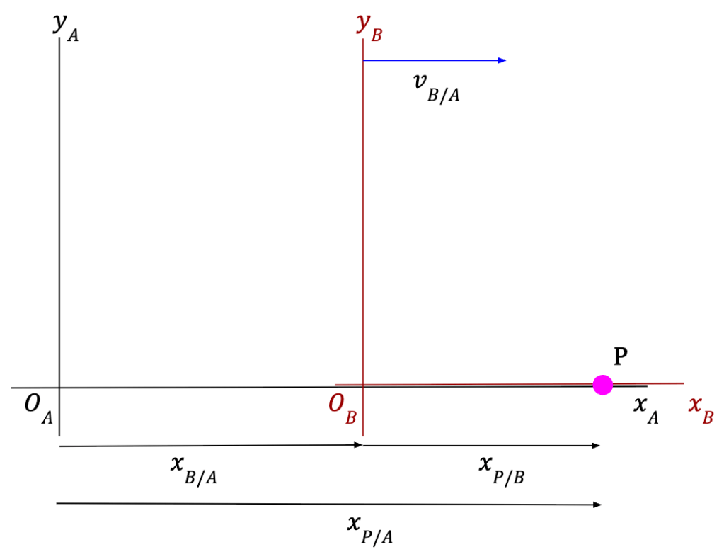
If xP/A represent the position of P relative to A, xP/B represent the position of P relative to B and xB/A represent the position of origin of B with respect to origin of A, then in straight-line motion (as seen in Figure 21) we can say:
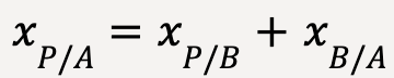 …..(38)
Taking derivative with respect to time on both sides, we get:
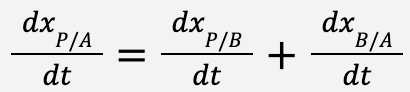 ……(39)
 ……(40)
Thus, the relative x-velocity of P with respect of A is given by the sum of relative x-velocity of P with respect to B and relative x-velocity of B with respect to A.
Since it is an algebraic sum, relative velocities can be negative. For example, if car (B) is moving backwards (-x-direction) with a velocity of -5.0 m/s and the ball (P) is moving forwards (+x-direction) with a velocity of +1.0 m/s, then the velocity of the ball relative to the stationary observer (A) will be: +1.0 m/s -5.0 m/s = -4.0 m/s.
Additionally, it is important to know the relationship between the relative velocities of two objects, say A and B with each other.
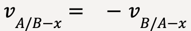 …..(41)
This is why when a person in a moving train looks outside the window at a tree (at rest with respect to the ground), the tree seems to move backwards!
Relative Velocity in Two or Three Dimensions
Similarly, for higher dimensions,
Let A be a stationary observer/frame of reference (at rest with respect to ground) and B be a moving frame of reference (moving with respect to the ground), for example, a van. Let P be an object moving on B, for example, a ball moving inside the van.

The position vectors can be written as follows:
 …..(42)
Taking time derivative of this equation:
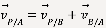 …..(43)
Equation (43) is referred to as Galilean Velocity Transformation.
And once again, for two frames of reference A and B,
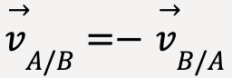 ……(44)
- Young, H.D. et al. (2016) Sears and Zemansky’s university physics: With modern physics. 14th edn. Boston: Pearson. ↩︎
- Note: the unit vectors do not depend on time. This means that the derivative of a unit vector with respect to time will be zero. ↩︎
- Becomes important when landing using a parachute. ↩︎
- Becomes important when firing long-range missiles. ↩︎
- Since acceleration is constant, this means that the velocity changes with equal amount in each interval along the y-direction. ↩︎
- Note: if air resistance is considered, the trajectory will not be parabolic and much complicated to determine. ↩︎
- The perpendicular component of acceleration never acts outwards to the curve. ↩︎
- Note: For circular motion, the perpendicular component of acceleration is referred to as the radial component of acceleration and the parallel component of acceleration is referred to as the tangential component of acceleration. ↩︎
- The rules have to modified if the velocities approach the speed of light because nothing can travel faster than the speed of light. The modified rules are defined by Einstein’s special theory of relativity. ↩︎
